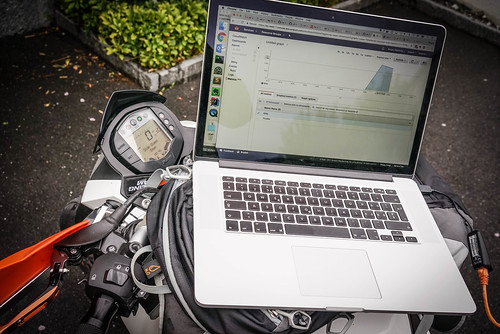
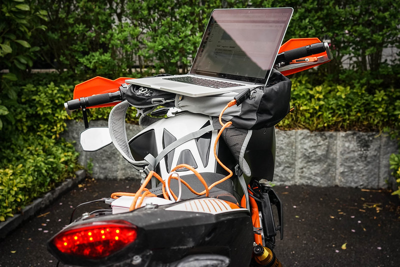
In this second post I continue with the short hackathon project I worked on last week. The goal of the project was to hook into engine data of a KTM motorcycle and stream that data in real-time to the cloud. I explain how I reverse engineered the USB wire protocol of a proprietary device called Power Commander 5 from Dynojet and wrote a simple Java program that works on Linux. I also show the tools I used along the way and share my thinking process.
The project source code is available at github. You’re welcome.
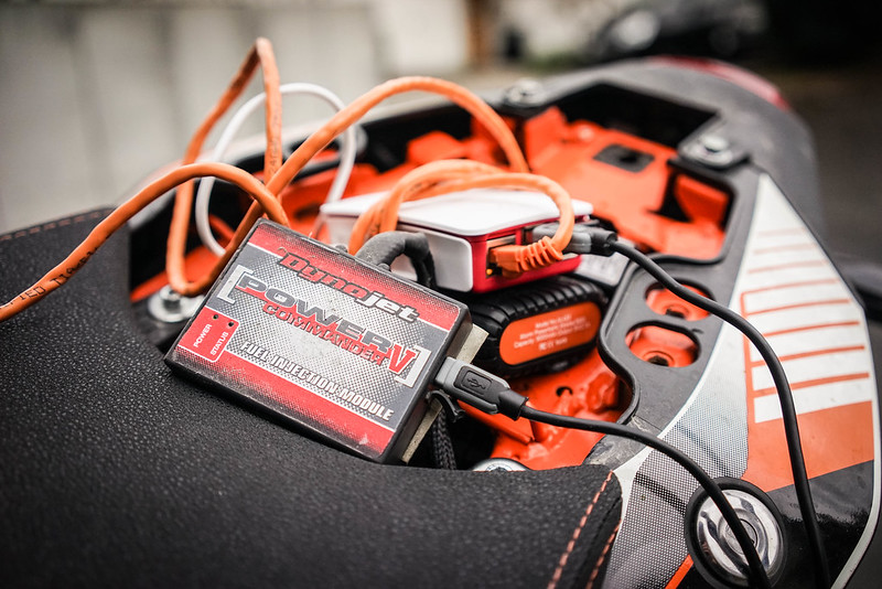
Power Commander 5
I introduced what Power Commander 5 (PCV) is in the first post. It is a third-party module that alters engine fuel injection by intercepting and changing ECU data. It is a programmable computer that adjusts engine behavior on the fly according to a configuration uploaded by the user (called a “map”). PCV has a micro USB port and works with a provided tool for Windows. The underlying USB protocol is not documented and there is no known API to speak of. It is a closed-source proprietary system which works only with the official software.

To extract the data I was after I needed to understand how the PCV interacts with the Windows tool and then write a program that mimics the behavior. Reverse engineering USB devices is nothing new. This has been done before to create Linux drivers for devices that didn’t have official support. The process of reverse engineering simpler devices, such as toy cars and toy missile launchers, has been documented extensively (Drive it yourself: USB car (Linux Voice)). The plan looked like the following:
- Look at the USB traffic between the PCV and its official software
- Capture USB traffic while changing one variable at time (e.g. giving throttle) while keeping everything else constant
- Analyze gathered captures to figure the general protocol and structure
- Analyze the captures to see where the useful data is (i.e. which bits represent RPM values)
Once the protocol was understood it remained to write a Java program for the Raspberry Pi 3 that established a USB connection and communicated with the PCV.
Monitoring and capturing USB traffic
To capture USB traffic I relied on Windows tools. Most of the articles I found used Linux instead. The suggested path is to run Windows OS inside a virtual guest on a Linux host computer. USB traffic would be captured at the host level. The problem was that I couldn’t pass the PCV from host to the guest. Since I had a Windows computer handy I decided to use it instead. As a first step I collected basic USB information about PCV. It turned out to be a USB HID class device. USB defines several classes of devices. Each USB class defines functions that manufacturers can use to communicate with devices. HID is normally used for keyboards, mice and various controllers. It’s also frequently used in simple USB toy gadgets.
After a quick survey of existing USB traffic capture tools I initially settled on a trial version of Eltima USB Analyzer. At first, the packet field names and terms were confusing. How does “direction” differ from “data_direction” and what is “TransferBuffer”? I had to look-up Windows USB API documentation to understand what those terms referred to. The UI of the software also left a lot to be desired. For example, I had to manually resize columns in the “Command View” to make the data visible. By default, the columns were too small.
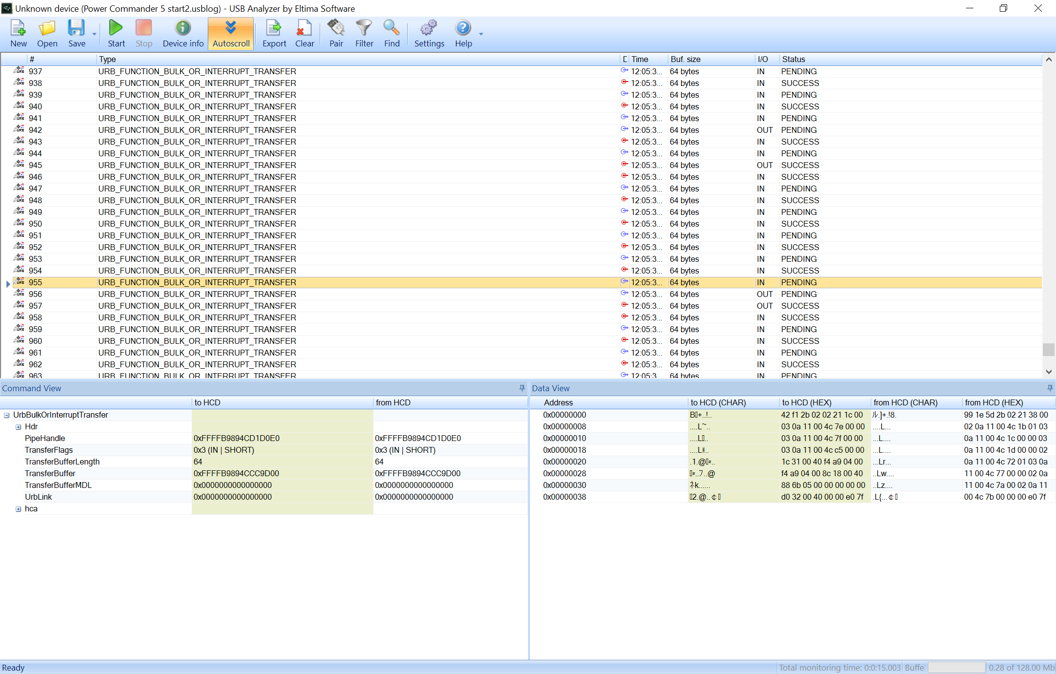
I couldn’t get any insight just by looking at the tool output. I didn’t realize that the actual packet data was in the bottom right panel and thought the data is stored in “TransferBuffer”. I exported the data using JSON. I then wrote a Java parser to try to wrap my head around the data. Throughout the project I wrote at least a couple of various parsers. It’s probably impossible to understand a binary protocol just by looking at random packets. I was looking for patterns. But I was clearly focused on the wrong piece of data. At least I learned that PCV communicates using URB (USB Request Blocks) bulk transfers – relatively large messages transferred on the USB bus.
After a dead end I looked for another tool and found HHD Device Monitoring Studio. HHDDMS is much better. From the statistics view I learned immediately that the number of packets exchanged between PCV and Windows tool stays constant. Giving gas or starting the engine didn’t change the rate of messages. This was in contrast with simple toy gadgets that typically don’t send data unless an action is triggered (e.g. button pressed in the app). That meant that data must have been constantly streamed.
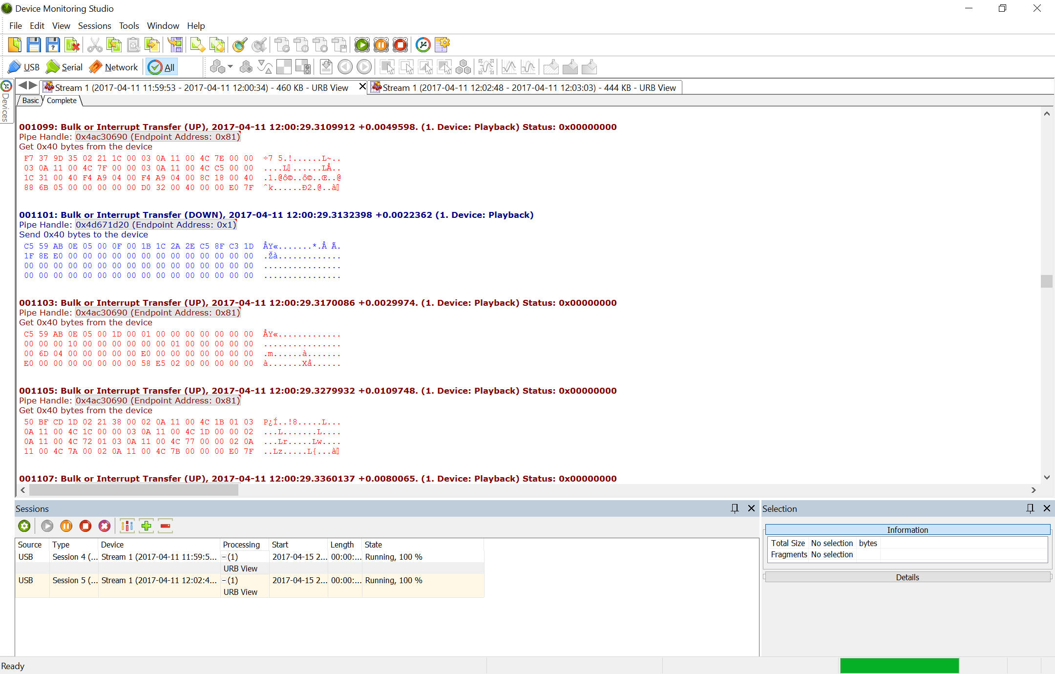
In the “URB” view of HHDDMS I could also see messages exchanged between the app and the PCV.
Still, it didn’t make much sense. Every packet appeared somewhat random and some packets even contained interspersed strings (e.g. “Dynojet”, “Device error”) that looked like they came from a resource bundle. It turned out later that these strings were just random junk to fill 64 byte packets. At the time I feared another dead end. Unexpectedly, a breakthrough came through Android. What does Android have to do with this?
Android breakthrough
Turns out Dynojet released an Android app in 2015 to interface with PCV from smartphones and tablets. Unfortunately, the app didn’t have the functionality I was after – it didn’t expose real-time statistics but otherwise it was impressively functional. Still, the basic routines to communicate with PCV should have been there. The thing with Android apps is that it’s extremely easy to decompile them to human readable form. So I downloaded the *.apk file, ran it through dex2jar and opened it in Lyuten. The results were better than expected – by looking at the decompiled code I could understand enough about how the USB packets were constructed. It was the right missing puzzle piece.
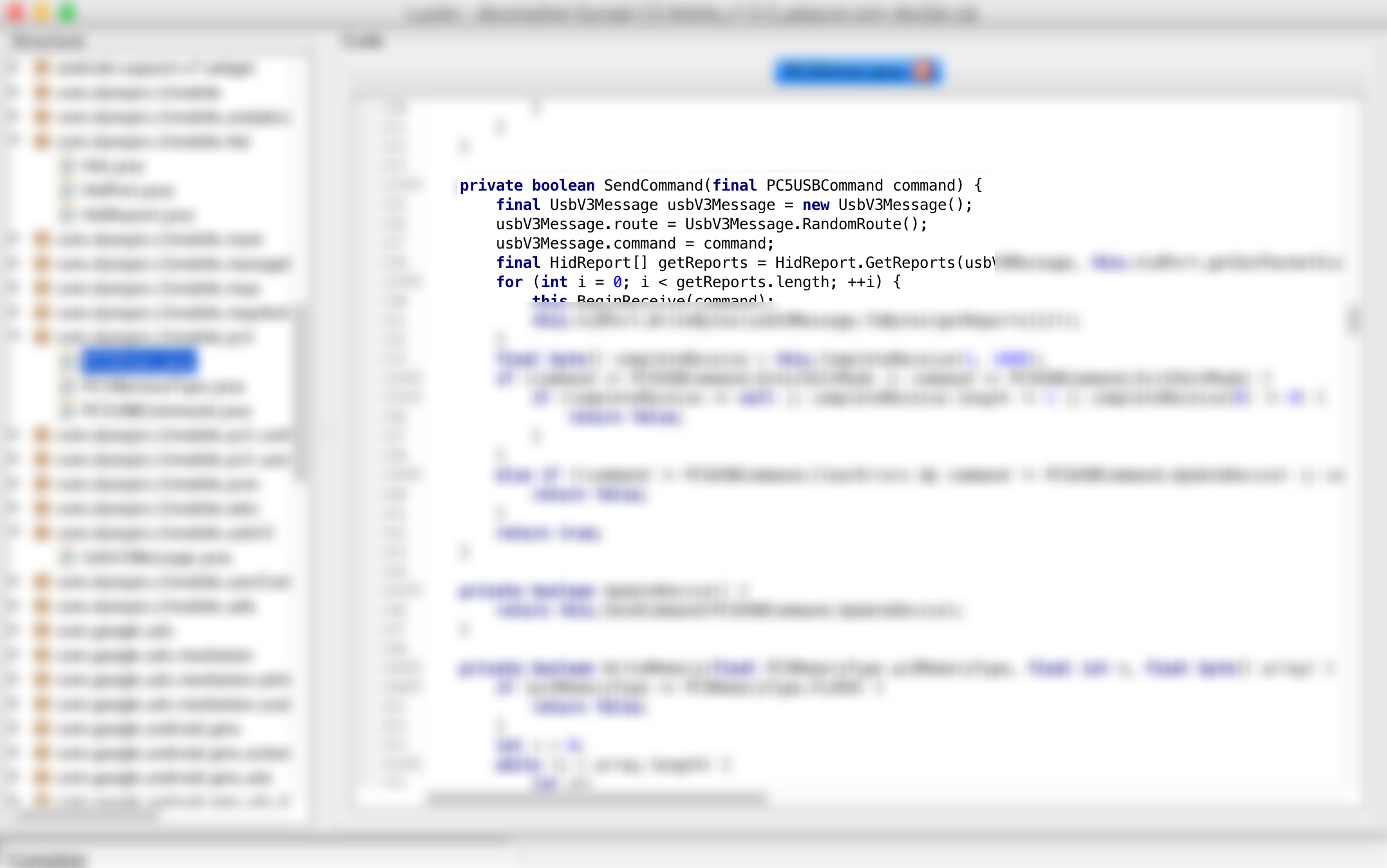
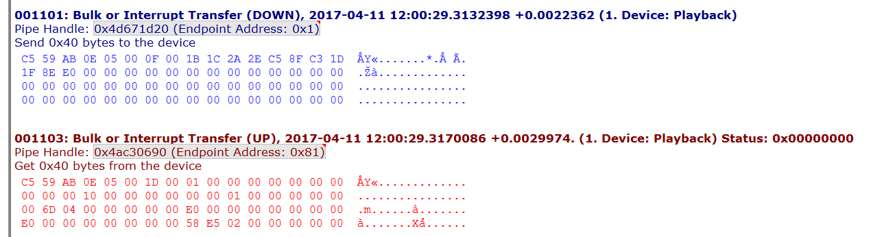
PCV USB packets are formed the following way. First 4 bytes are filled with a random integer (which had confused me earlier), followed by 2 bytes command ID, followed by 2 bytes payload length, followed by payload and finally followed by random junk to fill a 64 byte packet. What’s unusual is the little endian order. So, for example, “0x0500” is decoded as 5 and not as 1280. To convert to decimal one needs to reverse the bytes first, i.e. “0x0005”. Existing command IDs can be learned from the decompiled Android code. If anyone is interested in writing a Linux version of the PCV software the Android app is a great source of knowledge.
Equipped with the knowledge I wrote yet another parser to analyze various packet captures I had made earlier to find where the RPM and throttle values are “hidden”. Finally, it occurred to me that to obtain the data from PCV I must send command “5” to it first. Then, the PCV responds with the data. The random integer is used in the protocol to associate requests with responses. If I make a request packet “0x C5 59 AB 0E …” the PCV also responds with “0x C5 59 AB 0E …”.
Putting it all together
With the protocol figured out it remained to write a program that communicates with PCV over USB. I used usb4java Java library. It took me a couple of iterations to understand what the different concepts mean (e.g. pipe, connection) but the few available code examples were sufficient.
Here’s a demonstration of the program running on Raspberry Pi 3. The program prints out extracted RPM and throttle values. While recording the video I rolled the throttle on the bike and you can see the values increase (the throttle value range is 1..1000). The engine was turned off so the RPM read-out is 0.
I enjoyed the research part of the project immensely. It was the part of the project I enjoyed the most. Figuring out a binary protocol felt like detective work. Although there were confidence valleys and dead ends I pressed on and made it work. I look forward to more challenging projects in future.
I imagine that my progress in reverse engineering Power Commander 5 interface is potentially reusable so please help yourself and do something with it if you want – the code is published on github.
…to be continued in part 3.